Now Reading: POCO X3 GT Charging Port Replacement Guide
-
01
POCO X3 GT Charging Port Replacement Guide

POCO X3 GT Charging Port Replacement Guide
If your phone is not charging properly, charging cable feels loose, fast charging stops working, or your device is not detected by a computer, the charging port board may be damaged or worn out. In this detailed DIY repair guide from Geardo, you will learn how to safely replace the charging port board on the POCO X3 GT, also known as the Redmi Note 10 Pro 5G.
Built under the smartphone ecosystem of Xiaomi and released globally through the POCO lineup, this device uses internal flex cables and antenna connections that require careful handling during disassembly.
This guide explains every step clearly so beginners and intermediate repairers can perform the repair safely.
⭐ Repair Difficulty
★★★★★ (4 / 5 — Moderate Difficulty)
Estimated Repair Time: 45 — 70 Minutes
Device Type: Smartphone
Repair Type: Charging Port Board Replacement
Reasons for Charging Port Board Replacement
You may need to replace the charging port board if:
- Phone not charging or charging intermittently
- Charging cable feels loose or disconnects easily
- Fast charging not working
- USB connection not recognized by PC
- Moisture or corrosion damage
- Charging port physically damaged
Before You Begin
Compatibility and Model Numbers
- POCO X3 GT
- Xiaomi REDMI NOTE 10 Pro 5G (China)
Model Numbers : 21061110AG,
Tools Required
- Mobile phone heating pad or hairdryer/heat gun
- Plastic pry tool / card pry
- Suction cups
- Phillips #00/#000 screwdrivers
- Torx (T2/T3/T4) screwdrivers (Region Based)
- Flathead screwdriver
- Tweezers (for connectors)
- B7000 glue or double-sided adhesive (for back cover)
- Rubber bands or bonding clips to secure the back cover
How to Find Tools and Parts
- Heating pad – https://amzn.to/3H0tHzJ
- Portable Heat Gun – https://amzn.to/4mszih1
- Clamps https://amzn.to/3GYJT4w
- STREBITO 142 Piece Repair Tool Kit https://amzn.to/3UO1jUx
- Glue | Adhesive https://amzn.to/46exVxe
- Compatible Parts –
- Battery – https://amzn.to/4cE2oIH
- Screen – https://amzn.to/3OifDox
- Other Parts – https://amzn.to/40iRHDU
- Silicone Work Repair Mat https://amzn.to/45Emz5l
Step-by-Step Charging Port Board Replacement
Step 1 — Power Off the Device
Completely power off the phone before beginning the repair to avoid short circuits or accidental damage.
Step 2 — Heat the Back Cover
The back cover is secured using strong adhesive.
Heat gently around the edges until adhesive softens.
Recommended heating methods:
- Heating pad (recommended)
- Heat gun
- Hair dryer
Place the phone back-cover side down on a heating pad and allow the heating cycle to complete.
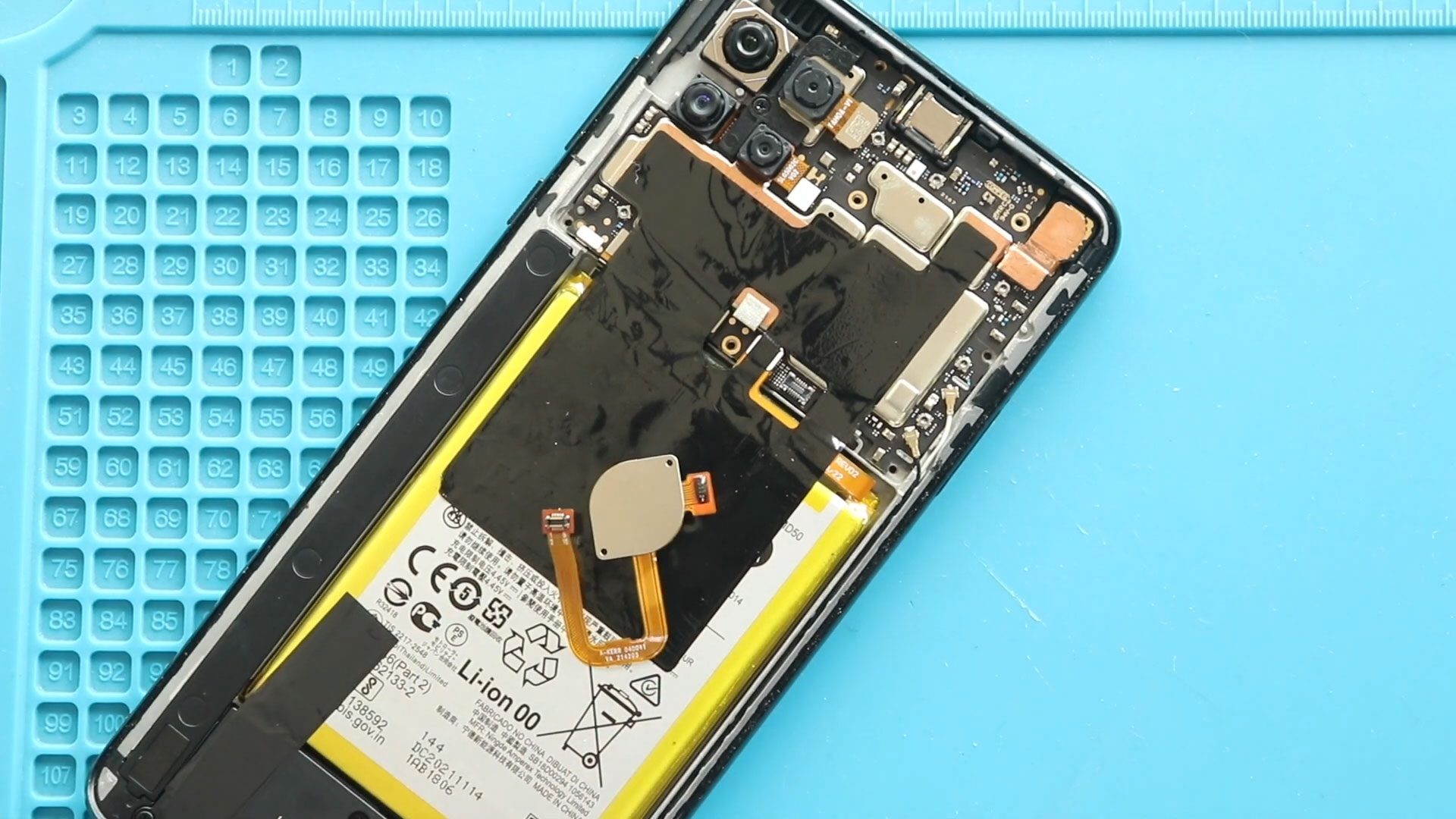
Step 3 — Remove Back Cover
Attach a suction cup near the edge.
Create a small opening.
Insert a plastic pry card.
Slowly slide around edges to cut adhesive.
Carefully remove the rear cover.
Step 4 — Remove Mid-Frame Screws
Remove 16 screws located on the top and bottom sections.
Keep screws organized.
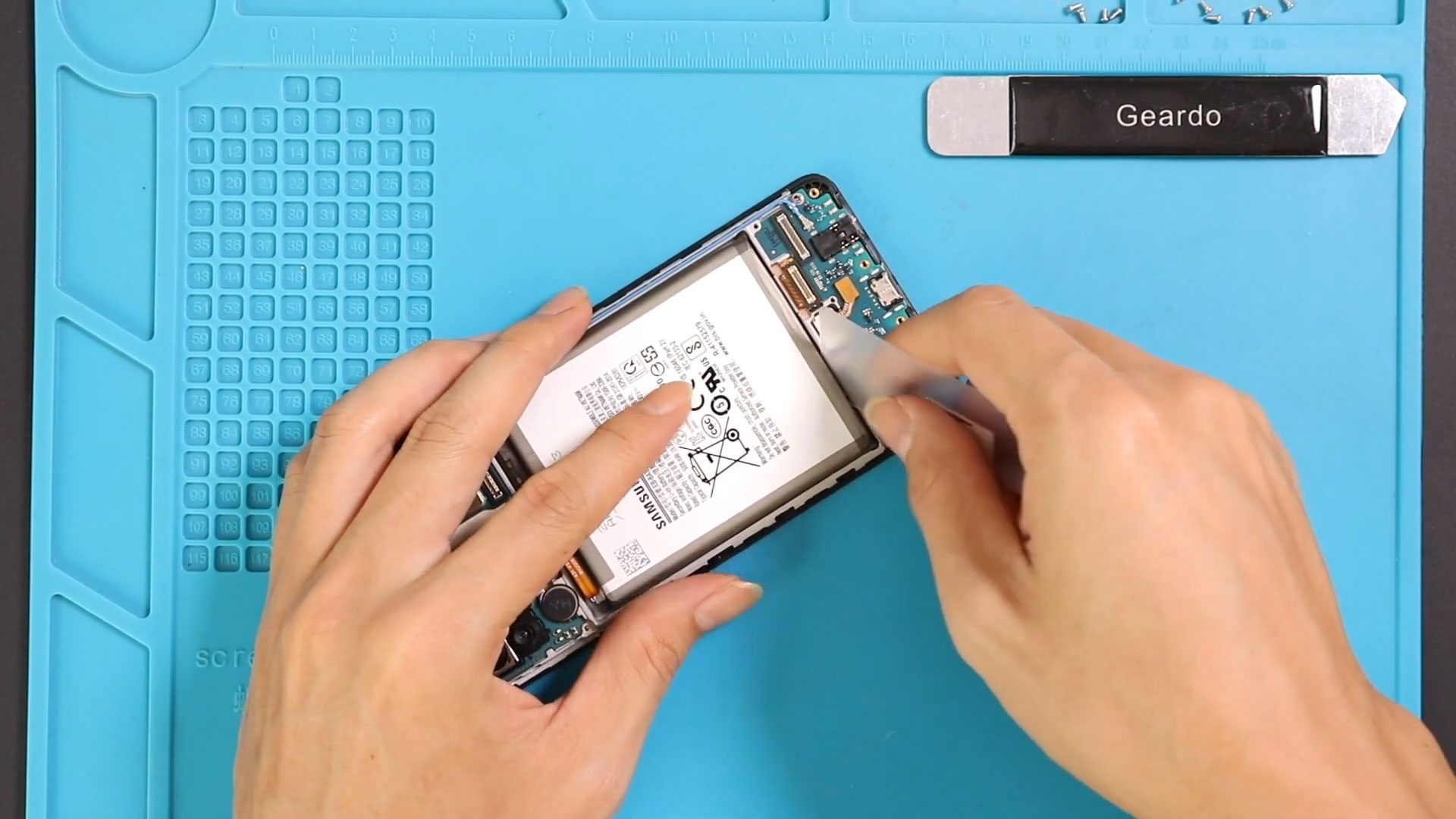
Step 5 — Separate Mid-Frame
Use a plastic pry tool to release plastic clips around the edges.
⚠️ Important:
The fingerprint sensor flex cable connects the mid-frame.
Disconnect the fingerprint flex cable carefully.
Disconnect the battery connector as well.
Remove the mid-frame completely.
Step 6 — Remove Speaker Buzzer Assembly
Move to the bottom section.
Carefully lift and remove the loudspeaker buzzer module.
This exposes the charging port board.
Step 7 — Remove Charging Port Board
Disconnect the following components:
- Secondary battery connector
- Secondary LCD flex cable
- Two antenna connectors
Lift and remove the faulty charging port board carefully.
Step 8 — Install New Charging Port Board
Place the replacement charging port board into position.
Reconnect:
- Both antenna connectors
- Secondary LCD connector
- Secondary battery connector
Ensure connectors click firmly into place.
Step 9 — Reinstall Speaker and Antenna Board
Place the speaker buzzer back into the housing.
Reinstall the left antenna board properly.
Ensure correct alignment.
Step 10 — Reconnect Connectors
Reconnect:
- Fingerprint sensor flex cable
- Battery connector
Double-check all connections.
Step 11 — Test Before Reassembly
Place the mid-frame temporarily.
Power on the device.
Check:
- Charging function
- Cable connection stability
- USB detection.
Turn the device off again after testing.
Step 12 — Secure Mid-Frame
Install the mid-frame fully.
Secure using sixteen screws.
Make sure everything sits flush.
Step 13 — Prepare Back Cover Adhesive
Inspect adhesive condition.
If adhesive is weak:
- Apply B7000 glue, OR
- Install new double-sided adhesive.
Step 14 — Close Back Cover
Press evenly around edges.
Use binding clips or rubber bands.
Leave secured for some time until adhesive bonds properly.
Repair complete.
Frequently Asked Questions (FAQ)
Q1. What are common signs of a damaged charging port board?
Loose cable connection, slow charging, or charging interruption usually indicates board failure.
Q2. Can I clean the charging port instead?
Yes. Try cleaning first. Replace the board only if cleaning does not solve the problem.
Q3. Why disconnect the battery first?
It prevents short circuits when disconnecting flex cables.
Q4. Should I test before sealing the phone?
Yes. Always test charging before reinstalling the back cover.
Q5. Is heating required?
Heating prevents glass cracking by softening adhesive.
Troubleshooting (After The Repair)
Q1. Phone not charging after replacement?
Check antenna and battery connectors again.
Q2. USB cable not detected?
Ensure LCD secondary connector and charging board are properly seated.
Q3. No signal after repair?
Check antenna heads carefully.
Q4. Back cover not sticking?
Apply new adhesive or B7000 glue evenly.
Q5. Charging works but fast charging not working?
Try another cable or adapter before reopening the device.
Related Guides