Now Reading: Samsung Galaxy A17 5G Charging Port Replacement Guide | Fix Microphone Issues
-
01
Samsung Galaxy A17 5G Charging Port Replacement Guide | Fix Microphone Issues
Samsung Galaxy A17 5G Charging Port Replacement Guide | Fix Microphone Issues
Having trouble charging your Samsung Galaxy A17 5G? Does the charging cable only work when held at a certain angle, or are callers unable to hear your voice clearly during phone calls? These issues are commonly caused by a damaged charging port board.
The charging port board in the Samsung Galaxy A17 5G houses both the USB-C charging port and the primary bottom microphone. Replacing this component can resolve charging failures, unstable USB connections, microphone issues, and other related problems without replacing the entire phone.
This beginner-friendly repair guide will walk you through the complete process of removing the damaged charging port board and installing a replacement assembly. Work carefully and take your time during each step to avoid damaging connectors or flex cables.
Repair Difficulty
Difficulty: ⭐⭐⭐☆☆ (Moderate)
Estimated Time: 30–60 Minutes
Reasons for the Repair
You may need to replace the Samsung Galaxy A17 5G charging port board if you experience any of the following issues:
- You may need to replace the charging port board if you experience any of the following symptoms:
- Device does not charge.
- Charging is intermittent or frequently disconnects.
- USB cable feels loose in the charging port.
- Computer cannot detect the device through USB.
- Fast charging is not working correctly.
- Bottom microphone is not picking up your voice.
- Callers report muffled or distorted audio.
- Voice recordings sound weak or silent.
- Physical damage to the USB-C port.
- Corrosion or liquid damage around the charging connector.
Before You Begin
Compatibility and Model Numbers
This repair guide based on Samsung Galaxy AA17 5G Model. Also Compatible with Galaxy A17 4G version, M17 & F17.
Model Numbers | SM-A176B , SM-A176B/DS, SM-A176U, SM-A176U1, SM-A175F, SM-A175F/DS, SM-A175M, SM-A175M/DS, SM-A175F/DSB, SM-M176B, SM-M176B/DS, SM-E176B/DS
Tools Required
- Mobile phone heating pad or hairdryer/heat gun
- Plastic pry tool / card pry
- Suction cups
- Phillips #00/#000 screwdrivers
- Tweezers (for connectors)
- B7000 glue or double-sided adhesive (for back cover)
- Rubber bands or bonding clips to secure the back cover
How to Find Tools and Parts
- Heat Mat / Heating Pad – https://amzn.to/3H0tHzJ
- Best Portable Heat Gun – https://amzn.to/4cZYnhL
- Clamps – https://amzn.to/3GYJT4w
- STREBITO 142 Piece Repair Tool Kit – https://amzn.to/3UO1jUx
- Stronger Suction Cup – https://amzn.to/3UVb6YR
- Silicone Work Repair Mat – https://amzn.to/4euW6fs
- Must Have Glue | Adhesive – https://amzn.to/4uxhKog
- Compatible Parts –
- Battery – https://amzn.to/4u43ZwP
- Screen – https://amzn.to/4cGsXNf
- Other Parts – https://amzn.to/3P2eiCP
| Premium Electric Screwdriver Kit Fanttik 50 in 1 Mini Precision Electric Kit – https://amzn.to/49azZaT Recommended Fanttik Electric Repair Workstation – https://amzn.to/42X2Ifz |
Samsung Galaxy A17 5G Charging Port & Main Microphone Replacement
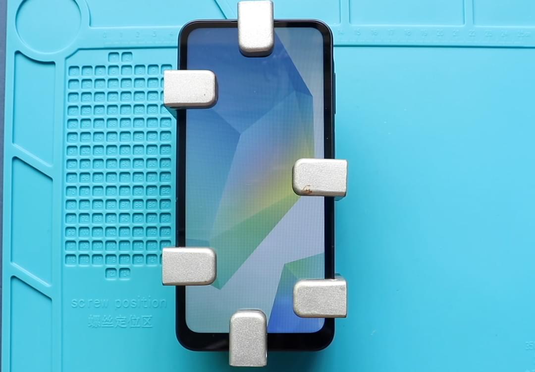
Step 1: Power Down the Device
Switch off the Samsung Galaxy A17 5G completely.
Remove the SIM card tray before beginning the disassembly process.
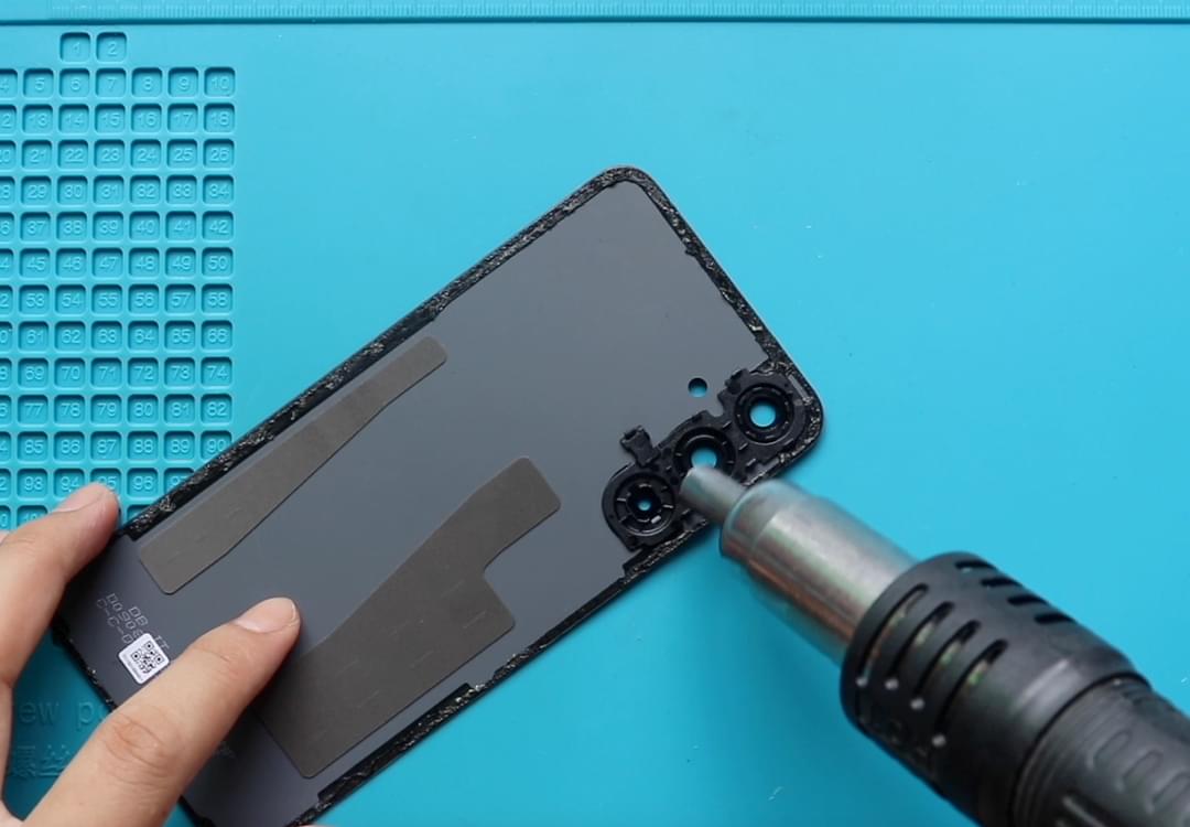
Step 2: Loosen the Rear Cover Adhesive
The rear cover is secured using strong factory adhesive.
Apply moderate heat around the perimeter of the back cover using a heating pad, heat gun, or hair dryer.
The goal is to soften the adhesive enough for safe removal.
Caution: Excessive heat can warp the back cover or damage nearby components.
Step 3: Remove the Back Cover
Attach a suction cup near the lower edge of the phone.
Create a small opening and insert a plastic card into the gap.
Work the card slowly around the outer edges to separate the adhesive.
Continue until the rear cover lifts free from the frame.
Set the cover aside in a clean area.
Step 4: Disconnect the Fingerprint Flex
Before removing the mid-frame, disconnect the fingerprint sensor flex cable attached to the power button assembly.
This prevents accidental damage when separating components.
Step 5: Remove the Internal Mid-Frame
Remove all fifteen Phillips screws securing the plastic mid-frame.
Using a plastic pry tool, release the retaining clips around the perimeter.
Carefully lift the mid-frame away from the device.
Take care not to force any section that remains clipped into place.
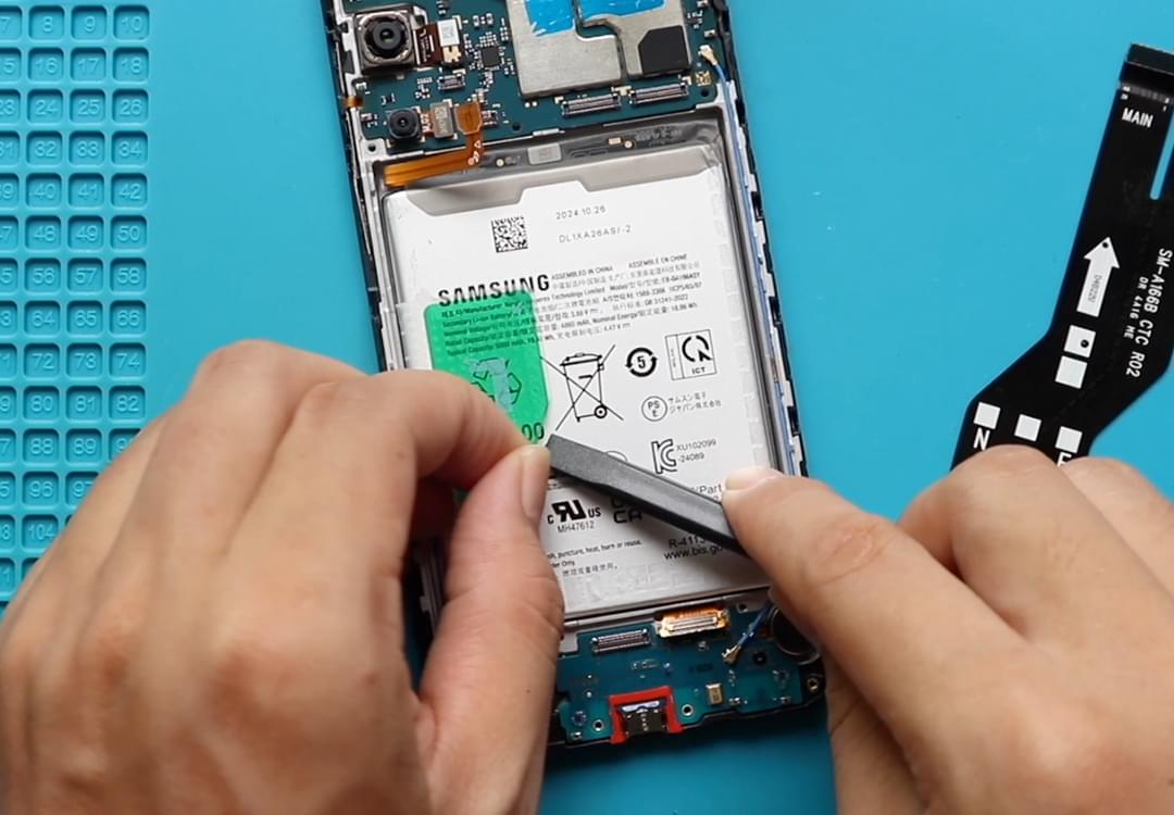
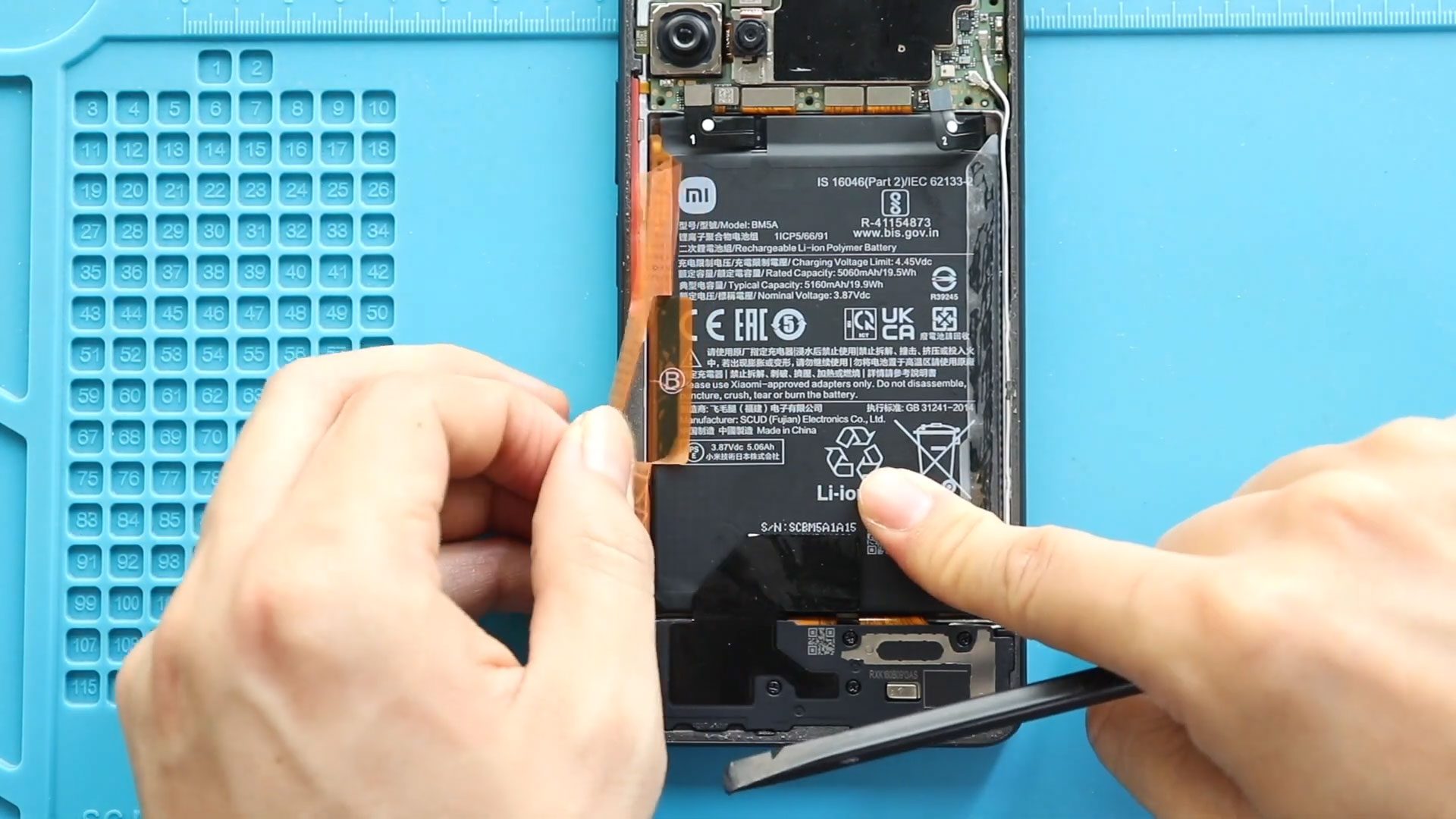
Step 6: Isolate Power from the Device
Locate the battery connector on the motherboard.
Disconnect the battery using a plastic pry tool.
This safety step should always be performed before servicing internal components.
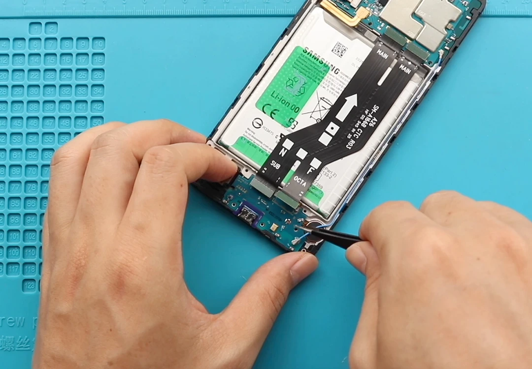
Step 7: Disconnect the Charging Board Connections
Locate the charging port board at the bottom of the device.
Disconnect:
- Main flex cable connector
- Secondary flex cable connector
- Antenna cable connection
Move the cables aside to gain full access to the board.
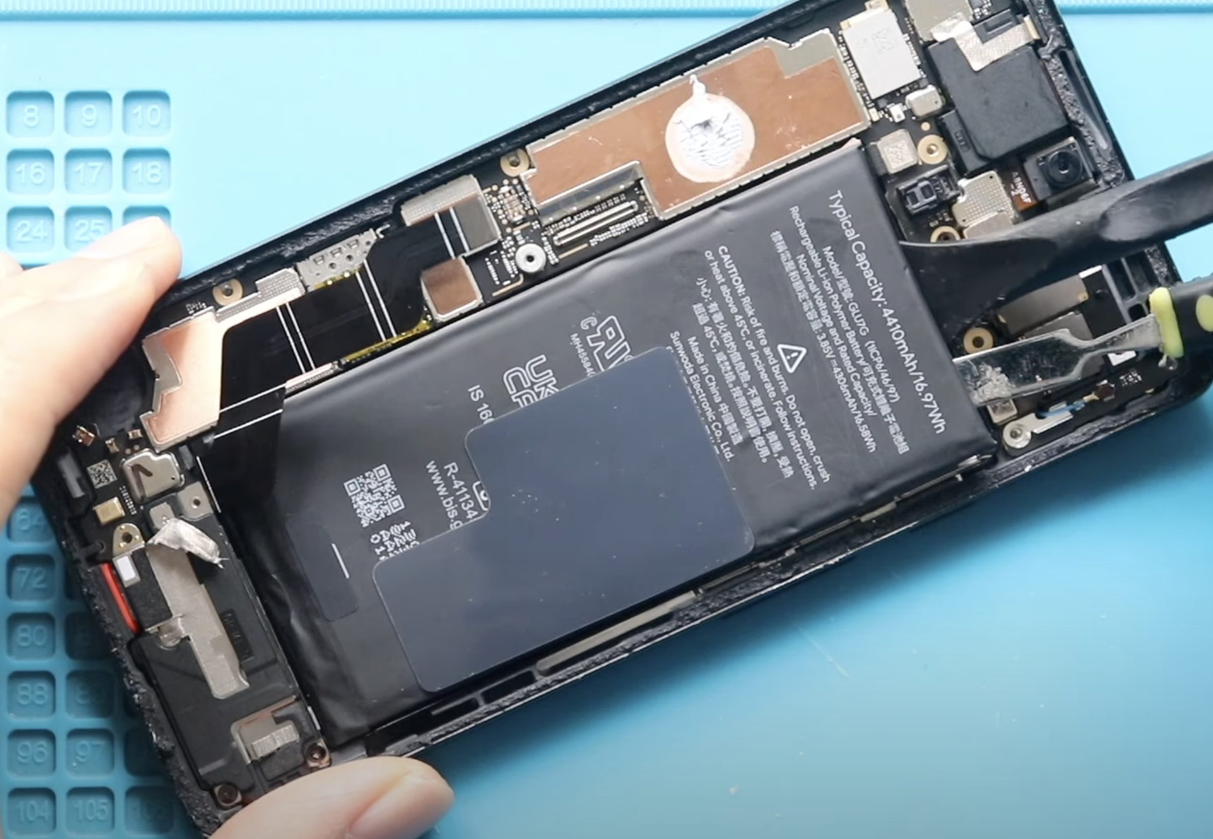
Step 8: Release the Display Connector
Part of the display flex cable is lightly adhered to the charging board assembly.
Apply a small amount of heat if necessary.
Carefully separate the display connector from the board without bending or damaging the flex cable.
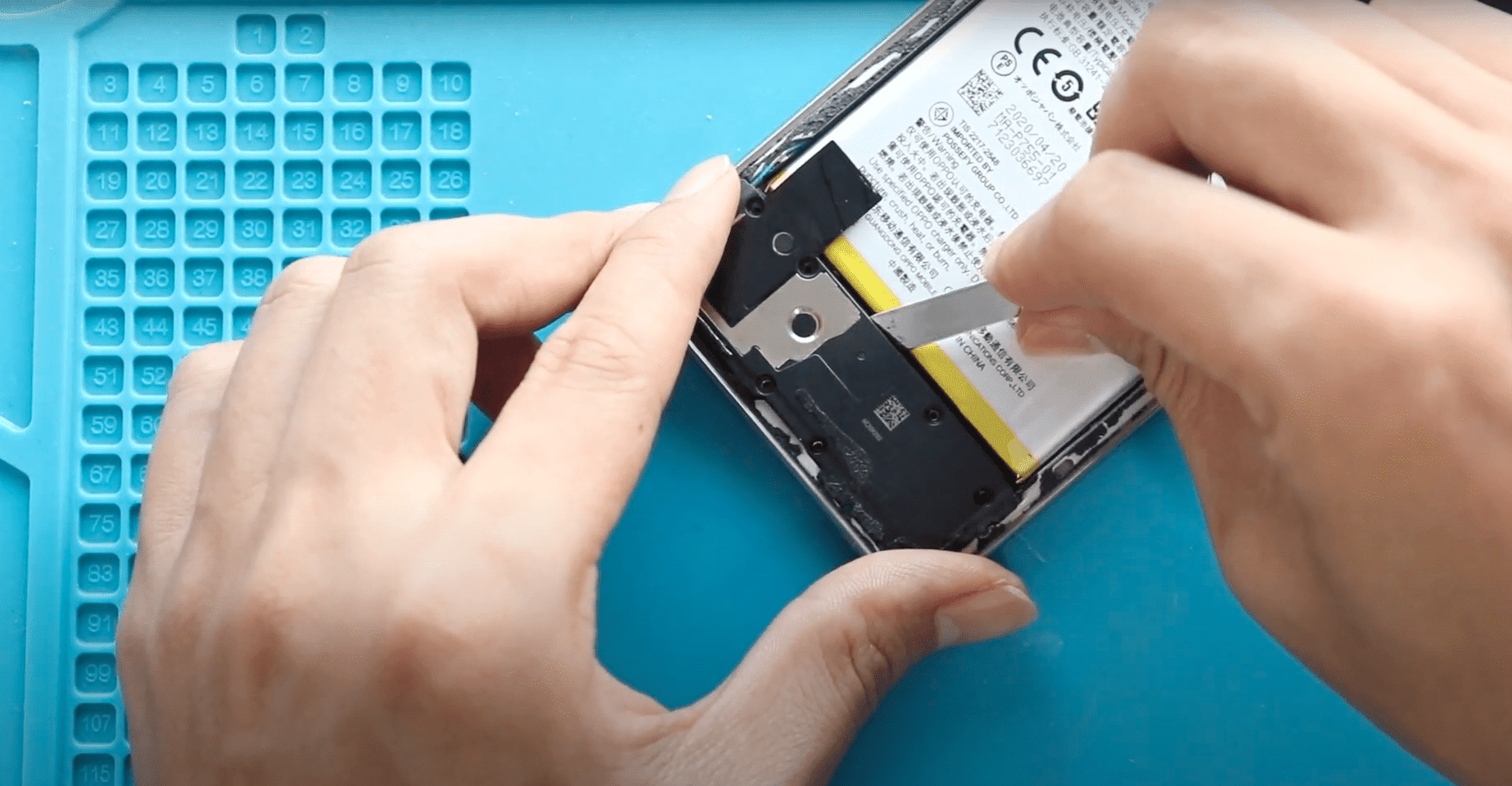
Step 9: Remove the Faulty Charging Port Board
Remove the retaining screw securing the charging board.
Lift the charging port board from the frame and remove it completely.
Inspect the microphone opening and surrounding area for dirt, dust, or adhesive residue before installing the replacement.
Step 10: Install the Replacement Charging Port Assembly
Position the new charging port board into the housing.
Ensure the USB-C port aligns correctly with the frame opening.
Secure the board with the retaining screw.
Reattach the display connector to its original position.
Reconnect both flex cable connectors.
Finally, reconnect the antenna cable.
Verify that every connector is fully seated before proceeding.
Step 11: Reconnect the Battery
Reconnect the battery connector to restore power to the device.
Perform a quick visual inspection of all connections before reassembly.
Step 12: Reinstall the Mid-Frame
Position the mid-frame over the phone.
Reconnect the fingerprint sensor flex cable.
Press around the perimeter until all clips lock into place.
Reinstall and tighten all fifteen screws.
Insert the SIM tray.
Step 13: Test Before Sealing
Power on the device before installing the rear cover.
Verify:
- Charging works normally.
- USB cable connection is stable.
- Fast charging functions correctly.
- Bottom microphone records clear audio.
- Phone calls transmit your voice correctly.
Complete testing now to avoid reopening the device later.
Step 14: Reattach the Back Cover
Apply fresh adhesive if the original adhesive no longer provides a secure seal.
Carefully align the rear cover.
Press firmly around the edges.
Use bonding clips or rubber bands to maintain even pressure while the adhesive cures.
Allow sufficient curing time before normal use.
Frequently Asked Questions (FAQ)
Q: Does replacing the charging port board also replace the microphone?
A: Yes. The primary bottom microphone is integrated into the charging port board assembly, so replacing the board typically resolves both charging and microphone issues.
Q: Why can people not hear me during calls?
A: A faulty bottom microphone, dirt buildup, liquid damage, or charging board failure can prevent your voice from being transmitted clearly.
Q: Can a damaged charging port affect fast charging?
A: Yes. Worn or damaged USB-C connectors often cause slow charging, charging interruptions, or complete charging failure.
Q: Do I need soldering equipment?
A: No. The Samsung Galaxy A17 5G charging port board is a modular component that can be replaced without soldering.
Q: Should I replace the adhesive after opening the phone?
A: Yes. Fresh adhesive helps maintain a secure fit and reduces the chance of dust entering the device.
Troubleshooting
Q: The phone still will not charge after replacing the board.
A: Check all flex cable connections, inspect the charger and cable, and verify that the replacement board is compatible with the Samsung Galaxy A17 5G.
Q: The microphone still sounds muffled.
A: Inspect the microphone opening for dust or debris and verify the replacement board was installed correctly.
Q: Fast charging is unavailable after repair.
A: Ensure the USB-C connector is fully aligned and test with a known working fast charger and cable.
Q: The computer does not recognize the phone.
A: Recheck the flex cable connections between the charging board and motherboard.
Q: The device will not power on after reassembly.
A: Verify the battery connector is securely connected and inspect all internal connectors for proper alignment.
Conclusion
Replacing the Samsung Galaxy A17 5G charging port board is an effective solution for charging failures, USB connectivity issues, and bottom microphone problems. By carefully following this guide and testing the device before sealing the back cover, you can restore reliable charging performance and clear voice communication without replacing the entire phone.
Related