Now Reading: DIY OnePlus 9 Charging Port Repair Guide
-
01
DIY OnePlus 9 Charging Port Repair Guide

DIY OnePlus 9 Charging Port Repair Guide
Before Starting, we need to have the right tools to proceed with the repair, which You can find in the description.
First, turn off the phone and take out the Sim tray, followed by the back cover removal.
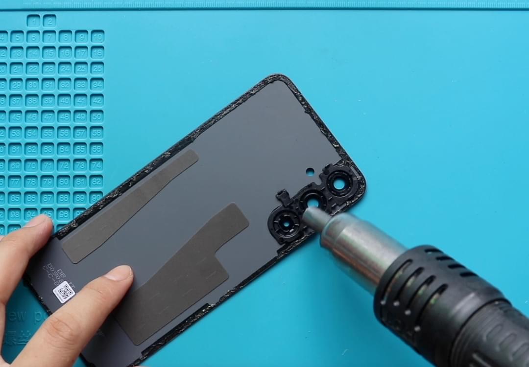
To remove the back cover, it needs to heat gently around the rear cover edges until the pasted adhesive becomes soft.
For this, we are using a heat gun,
Carefully work around on edges, and Once you feel the heating is enough,
use a suction cup to lift the back cover. In between, Insert a Plastic Card pry tool and gently cut the adhesive.
Take out the rear cover and take out the Main Board protector frame by undoing screws. First, Take out the shield and disconnect, and remove the flasher plug.
And then, Undo Nine screws and lift the board frame with the wireless coil using a pry tool.
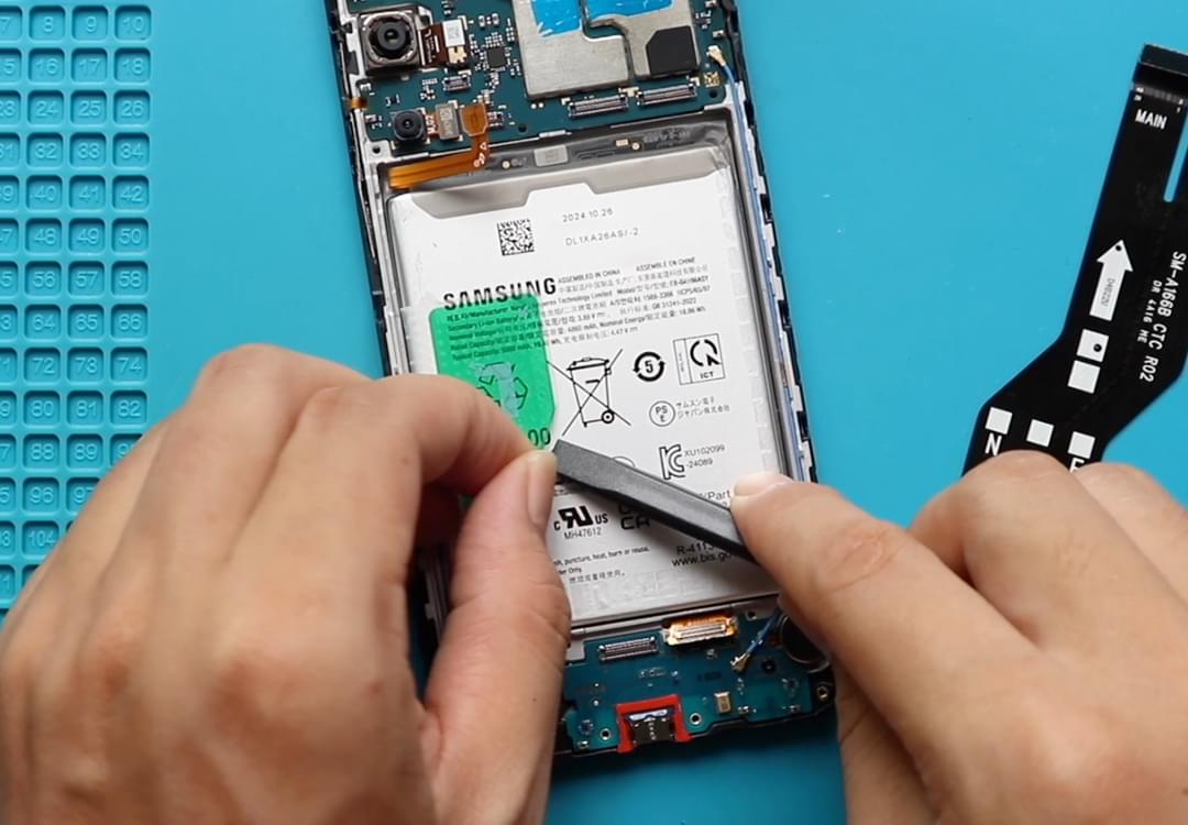
Next, from the right-hand side, disconnect the battery plug.
Next, Move to the Bottom section and undo Seven screws to take out the PCB cover.
Next, disconnect the top end of the main and charging port flex connector from the board.
Next, Take out the shield on the main flex and disconnect the bottom end on the main ribbon before pulling it out.
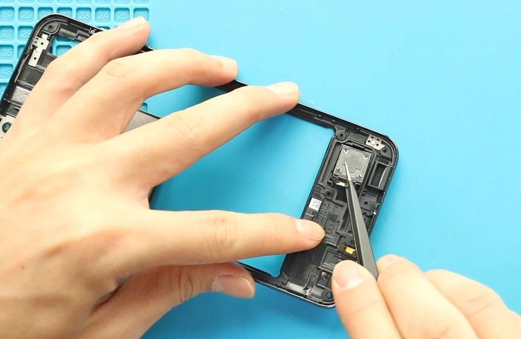
Next, take out the speaker buzzer and then disconnect the touch id flex connector and two antennas on the bottom PCB.
Next, undo one more screw and pull the bottom PCB, which includes the Sim card Tray.
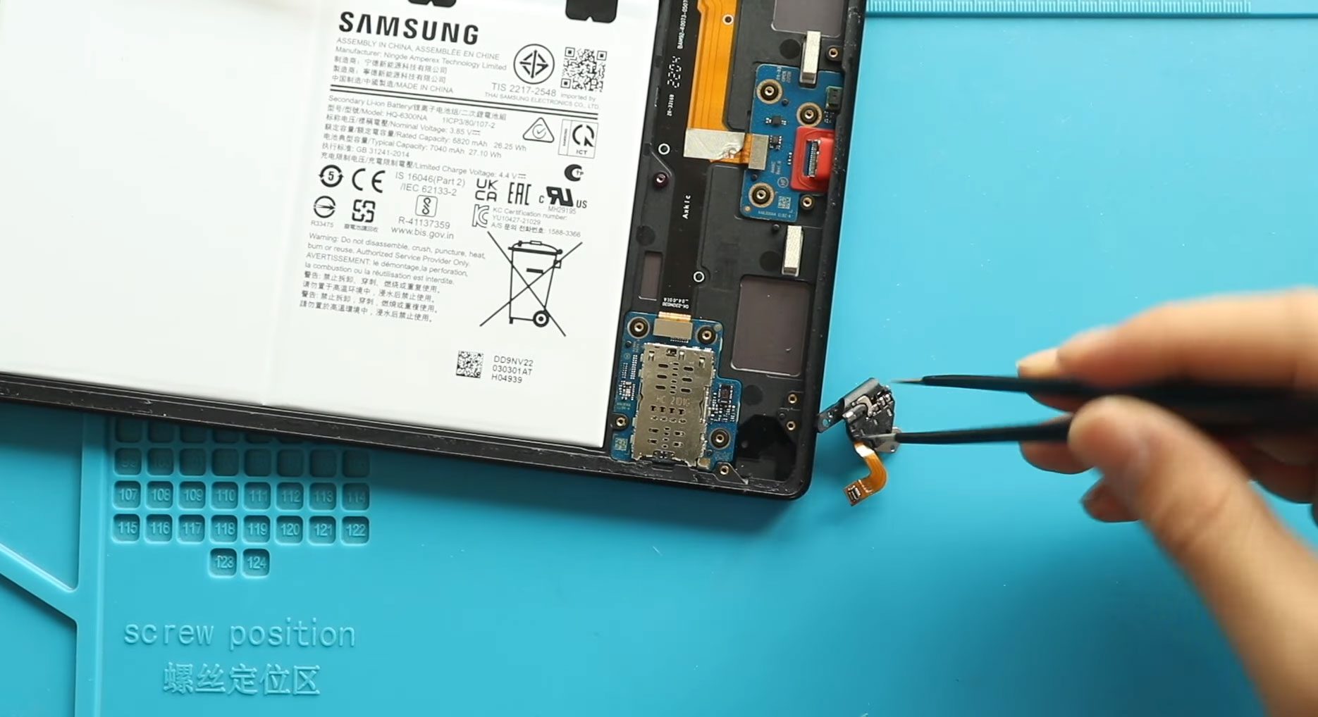
Next, Gently pull out the broken charging port flex cable from the body.
Next, place the New charging port flex on the body.
Next, place the speaker buzzer in the body and then place the bottom PCB in the body.
Next, secure the secondary board by screw, and then connect the touch id camera. Next, connect both antenna heads to the board.
Next, connect both ends on the main flex and secure the charging port to the mainboard.
Next, place the shield on the main ribbon flex and place the bottom PCB cover by adding seven screws.
Next, Secure the battery connector and then secure the logic board frame by adding nine screws. And also, make sure to connect the flash sensor and the shield.
Next, insert the sim tray and place the back cover on the body.
Before installing the main back cover, make sure it has enough glue on it; if not, use B7000 glue or a new double-sided back cover adhesive.
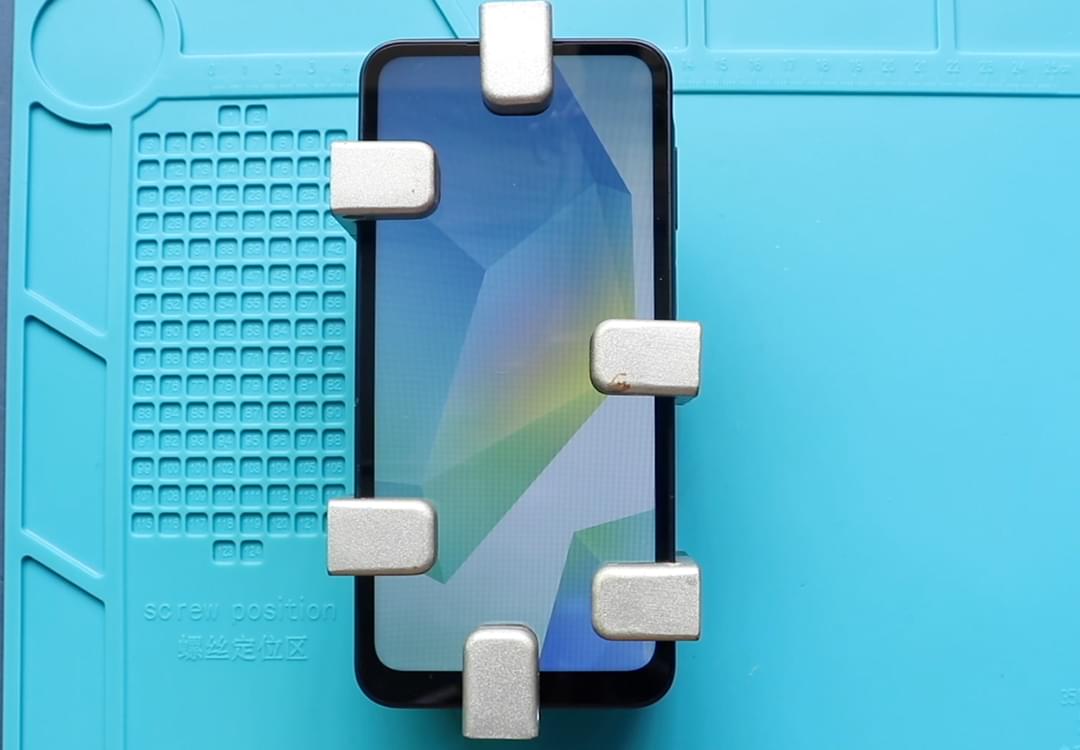
Finally, we are adding bonding clips to tightened the rear cover with the body. If not, you can use some rubber bands and Leave them for some time.
I hope you have enjoyed the replacement guide.Let us know if you have any questions.