Now Reading: Samsung Galaxy A17 5G Rear Camera Replacement Guide – DIY Repair
-
01
Samsung Galaxy A17 5G Rear Camera Replacement Guide – DIY Repair

Samsung Galaxy A17 5G Rear Camera Replacement Guide – DIY Repair
If your Samsung Galaxy A17 5G takes blurry photos, struggles to focus, displays a black screen when opening the camera app, or shows camera errors, one or more of the rear camera modules may be faulty. Physical damage from drops, liquid exposure, or failed camera components can affect image quality and overall camera performance.
The Samsung Galaxy A17 5G features multiple rear camera modules, including the primary wide camera, ultra-wide camera, and macro camera. Depending on the fault, you may replace an individual camera or all rear camera modules during the repair.
This guide walks through the process of accessing and replacing the rear-facing cameras while protecting the motherboard and surrounding components.
Repair Difficulty
Difficulty: ⭐⭐⭐☆☆ (Moderate)
Estimated Time: 30–50 Minutes
Repair Type: Rear Camera Replacement
Reasons for the Repair
You may need to replace one or more rear cameras if you experience:
- Blurry or out-of-focus photos
- Camera app crashes when opening
- Black screen in camera mode
- Camera failed warning messages
- Visible lens damage
- Shaking or vibrating image stabilization issues
- Water or liquid damage
- Scratched internal camera lens
- Poor image quality compared to normal operation
- One camera mode not functioning properly
Before You Begin
Compatibility and Model Numbers
This repair guide based on Samsung Galaxy AA17 5G Model. Also Compatible with Galaxy A17 4G version, M17 & F17.
Model Numbers | SM-A176B , SM-A176B/DS, SM-A176U, SM-A176U1, SM-A175F, SM-A175F/DS, SM-A175M, SM-A175M/DS, SM-A175F/DSB, SM-M176B, SM-M176B/DS, SM-E176B/DS
Tools Required
- Mobile phone heating pad or hairdryer/heat gun
- Plastic pry tool / card pry
- Suction cups
- Phillips #00/#000 screwdrivers
- Tweezers (for connectors)
- B7000 glue or double-sided adhesive (for back cover)
- Rubber bands or bonding clips to secure the back cover
How to Find Tools and Parts
- Heat Mat / Heating Pad – https://amzn.to/3H0tHzJ
- Best Portable Heat Gun – https://amzn.to/4cZYnhL
- Clamps – https://amzn.to/3GYJT4w
- STREBITO 142 Piece Repair Tool Kit – https://amzn.to/3UO1jUx
- Stronger Suction Cup – https://amzn.to/3UVb6YR
- Silicone Work Repair Mat – https://amzn.to/4euW6fs
- Must Have Glue | Adhesive – https://amzn.to/4uxhKog
- Compatible Parts –
- Battery – https://amzn.to/4u43ZwP
- Screen – https://amzn.to/4cGsXNf
- Other Parts – https://amzn.to/3P2eiCP
| Premium Electric Screwdriver Kit Fanttik 50 in 1 Mini Precision Electric Kit – https://amzn.to/49azZaT Recommended Fanttik Electric Repair Workstation – https://amzn.to/42X2Ifz |
How to Replace the Rear Cameras on Samsung Galaxy A17 5G
Step 1: Prepare the Device
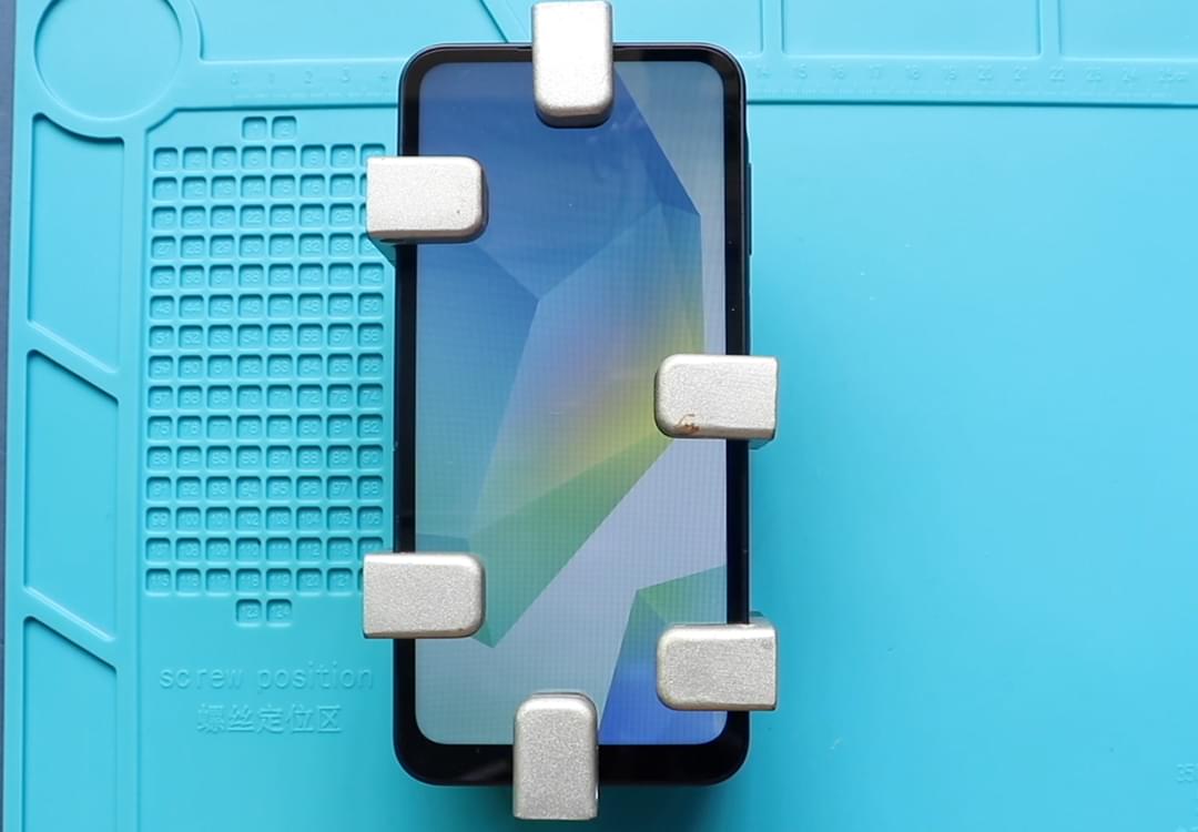
Power off the Samsung Galaxy A17 5G completely.
Remove the SIM card tray before beginning the repair.
This helps prevent accidental damage during disassembly.
Step 2: Open the Rear Cover
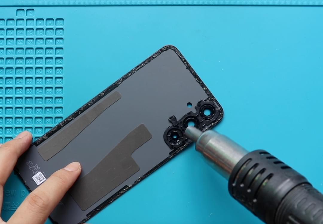
The back cover is secured using perimeter adhesive.
Apply moderate heat around the edges of the phone to soften the adhesive bond.
Using a suction cup and plastic opening card, carefully separate the rear cover from the frame.
Work around all sides until the cover can be removed safely.
Step 3: Disconnect the Fingerprint Sensor
Locate the fingerprint sensor flex cable attached to the rear cover.
Disconnect the cable before fully separating the back cover assembly.
Place the cover aside in a safe location.
Step 4: Remove the Protective Mid-Frame
Remove all fifteen Phillips screws securing the internal frame.
Using a plastic pry tool, release the retaining clips around the perimeter.
Carefully lift the mid-frame assembly away from the device.
Step 5: Disconnect the Battery
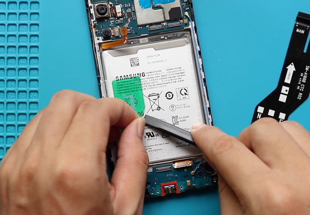
Locate the battery connector and disconnect it from the motherboard.
This prevents accidental short circuits while servicing the camera modules.
Replacing the Macro Camera
Step 6: Remove the Faulty Macro Camera
The macro camera is accessible without removing the motherboard.
Disconnect the camera connector from the logic board.
Carefully lift the camera module from its housing.
Inspect the connector area for dust or debris before installation.
Step 7: Install the New Macro Camera
Position the replacement macro camera into the camera housing.
Reconnect the camera flex connector and ensure it clicks securely into place.
Verify proper alignment before continuing.
Accessing the Main Rear Cameras
Step 8: Create Access to the Wide and Ultra-Wide Cameras
The primary wide camera and ultra-wide camera sit beneath the motherboard area.
Disconnect the main flex cable connections attached to the motherboard.
Remove the retaining screw securing the board.
Carefully lift and pivot the motherboard enough to gain access to the camera modules.
Avoid straining any connected cables.
Step 9: Remove the Wide and Ultra-Wide Cameras
Disconnect the camera connectors from the motherboard.
Lift the faulty camera modules from their mounting locations.
Take note of their original positions before installation.
Step 10: Install the Replacement Camera Modules
Position the replacement wide and ultra-wide cameras into the frame.
Ensure each camera sits correctly within its designated housing.
Reconnect the camera connectors securely.
Verify all modules are aligned properly before reinstalling the motherboard.
Step 11: Reinstall the Motherboard
Return the motherboard to its original position.
Reinstall the retaining screw.
Reconnect all previously disconnected flex cable connectors.
Inspect antenna routing and confirm cables remain seated correctly within the frame.
Step 12: Test the Cameras
Reconnect the battery temporarily and power on the phone.
Open the Camera application and test:
- Main camera
- Ultra-wide camera
- Macro mode
- Photo capture
- Video recording
- Focus performance
- Flash functionality
Confirm all camera modules operate normally before completing reassembly.
Step 13: Restore Battery Connection
Power off the device again if testing was performed.
Reconnect the battery connector securely.
Step 14: Reassemble the Device
Position the mid-frame onto the phone.
Reconnect the fingerprint sensor flex cable.
Press around the perimeter until all clips engage.
Reinstall all fifteen screws.
Insert the SIM tray.
Step 15: Reattach the Rear Cover
Inspect the original adhesive.
Apply replacement adhesive if necessary.
Align the rear cover and press it firmly into position.
Use bonding clips or rubber bands while the adhesive cures.
Allow sufficient time before regular use.
Frequently Asked Questions (FAQ)
Q: Can I replace only one rear camera?
A: Yes. Each rear camera module can typically be replaced individually if only one camera is faulty.
Q: Why does my camera show a black screen?
A: A failed camera module, damaged connector, motherboard issue, or software fault may cause a black camera preview.
Q: Why are my photos blurry?
A: A damaged lens, faulty autofocus system, or defective camera sensor can result in blurry images.
Q: Will replacing the camera improve image quality?
A: If the original camera module is damaged, a replacement can restore normal image quality and focus performance.
Q: Do camera modules require programming after replacement?
A: In most cases, rear camera modules are plug-and-play and do not require programming.
Troubleshooting
Q: The Camera app still crashes after replacement.
A: Check all camera connectors and verify the replacement camera modules are compatible with the Samsung Galaxy A17 5G.
Q: One camera works but another does not.
A: Reinspect the connector for the non-functioning camera and ensure it is fully seated.
Q: Photos remain blurry after installation.
A: Verify protective films have been removed from the replacement camera and check for debris on the lens.
Q: The camera image appears tilted or misaligned.
A: Confirm the camera module is seated properly within its mounting position.
Q: The phone will not boot after reassembly.
A: Inspect all motherboard connections and verify the battery connector is fully attached.
Conclusion
Replacing the rear cameras on the Samsung Galaxy A17 5G can restore photo quality, autofocus performance, and overall camera functionality. Whether you’re replacing a damaged macro camera, ultra-wide camera, or primary wide camera, following the proper disassembly and installation procedure helps ensure a successful repair and reliable camera performance.
Repair Guide